Introduction

This repair guide was authored by the iFixit staff and hasn’t been endorsed by Google. Learn more about our repair guides here.

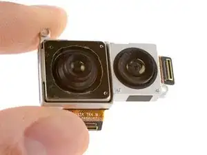
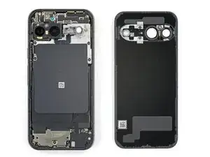
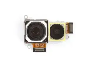
Use this guide to replace the rear camera module—containing both the wide and ultrawide cameras—in your Google Pixel 9.

If your photos appear distorted, blurry, or the camera just doesn’t function, it might be time to replace the rear cameras.

You'll need replacement back glass and autofocus sensor adhesives to complete this repair.

Note: Any repair can compromise the water resistance of your phone. Retaining water resistance after the repair will depend on how well you reapply the rear cover adhesive.

  1. t2WJlFY4B1vATsYN
    t2WJlFY4B1vATsYN
    jYHFHEiOpmlHNJnI
    BWKuEANpTs2VILmJ
    • Let your Pixel's battery drain below 25% before starting this repair. A charged lithium‑ion battery may catch fire if damaged.

    • Unplug all cables from your phone.

    • Completely power off your phone.

    • Press the power and volume up buttons at the same time to bring up the shutdown menu.

  2. OgPnJhERSSoRGA6L
    OgPnJhERSSoRGA6L
    2iwaZgHLal2kLyX5
    iHWvbrscyQIMPLNr
    • Adhesive secures the perimeter of the back glass to the frame.

    • When separating the adhesive, don't insert your tool more than 3 mm under the back glass to avoid damaging the internal components.

    • To help, measure and mark 3 mm from the tip of an opening pick with a permanent marker.

    • If your screen or back glass is badly cracked, a suction cup may not perfectly adhere.

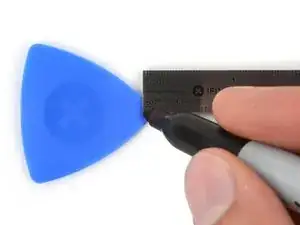
    • Lay overlapping strips of packing tape over the glass to protect yourself and make disassembly easier. Ensure there's a smooth area near the bottom edge that's large and smooth enough for a suction cup to stick to.

  3. QKDBYPCZbIkd5c5K
    QKDBYPCZbIkd5c5K
    ds1VWaxnhY2CIXuP
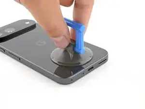
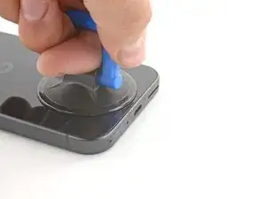
    • Place a suction handle at the bottom edge of the back glass, as close to the edge as possible.

    • Push down to attach the suction cup.

  4. WppPKcaOsanvNpsP
    WppPKcaOsanvNpsP
    KSWCkuxG1qHOprbH
    b1I2P2qIT1GxjWCF
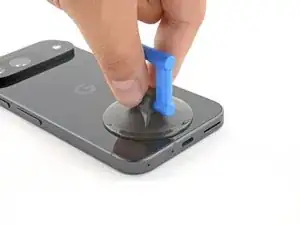
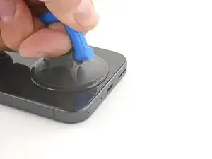
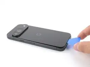
    • Pull up on the suction handle with strong, steady force to create a small gap under the back glass.

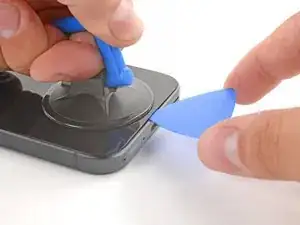
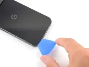
    • Insert the tip of an opening pick into the gap.

  5. K2BZZwRJOGTtbhuP
    K2BZZwRJOGTtbhuP
    PAyQbbwsdw6NwTrq
    pGDDGEoGcCtMCRXw
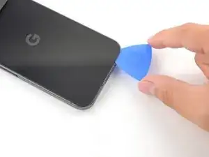
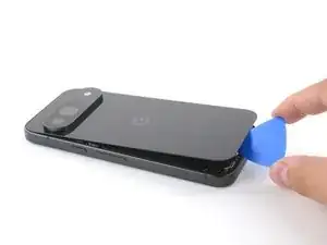
    • Slide the opening pick back and forth along the bottom edge to separate the adhesive securing it.

    • Remember: don't insert the opening pick deeper than 3 mm.

  6. 5tIMW2J6ULeITRJL
    5tIMW2J6ULeITRJL
    AFo26InHMAxnhp5X
    MYTMbQavDHrPdOX4
    • Slide the opening pick around the perimeter of the phone, slicing the rest of the adhesive.

  7. koORq5aw114fSFtj
    koORq5aw114fSFtj
    3FRZFCGSZU2KYqql
    Wy6Gg1pleHpAJ3BB
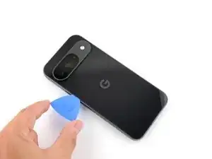
    • With most of the adhesive separated, lightly twist the opening pick at the bottom edge to lift the back glass up until you can grip it with your fingers.

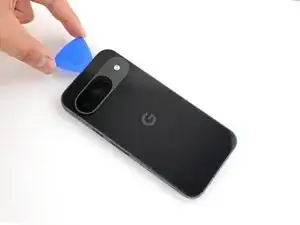
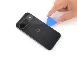
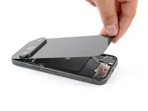
    • Use the opening pick to separate any remaining sections of adhesive securing the back glass.

  8. KHykH3NCssOgshVv
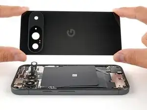
    • Remove the back glass.

    • During reassembly:

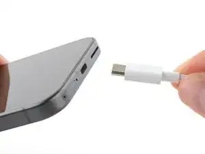
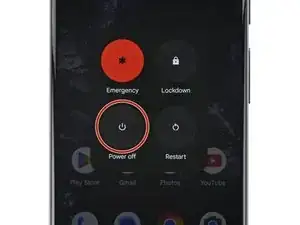
    • Now is a good time to test your phone before sealing it up. Power it on and check that it works. Power it back down before you continue reassembly.

    • Follow this guide to apply new adhesive and install your back glass.

  9. UAifQcWkJIq4VdFw
    • Throughout this repair, keep track of each screw and make sure it goes back exactly where it came from.

    • While the Pixel 9 uses Torx Plus screws, standard Torx bits also work. Make sure to apply constant, downward force to prevent stripping.

    • Use a 3IP Torx Plus driver to remove the single 5.4 mm‑long screw securing the upper board cover.

  10. lxT5avZqOxQjTgJF
    lxT5avZqOxQjTgJF
    uTnX6IH5I5HKsF4g
    • Use a pair of tweezers to remove the upper board cover.

  11. hFiysMfckwNfhsL1
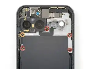
    • Use a 3IP Torx driver to remove the five screws securing the midframe and wireless charging coil:

    • Four 5.4 mm-long screws

    • One 2.2 mm-long screw

  12. jN4BcUDnOitOvdrQ
    jN4BcUDnOitOvdrQ
    1SlEVtAXvwX4hRSL
    • Use a pair of tweezers to peel the flash cable off of the metal midframe.

  13. s3Za52F5v2TEjnqc
    s3Za52F5v2TEjnqc
    5wSNXRBOAMvGYU2J
    • Remove the midframe, wireless charging coil, and NFC assembly.

  14. uWgyw3iNBauYBK1n
    uWgyw3iNBauYBK1n
    5QRQKp3qCQdtI3sw
    • Use the tip of a spudger to pry up and disconnect the battery connector.

  15. hdp5TBwU6TYOThus
    hdp5TBwU6TYOThus
    wsIbPTASYrLbOdQk
    b65dpTYAMrb4aiMs
    • Use the tip of a spudger to pry up and disconnect the 5G mmWave antenna's press connector.

  16. vBuh3SUxoCA4LTge
    vBuh3SUxoCA4LTge
    Z1rMRWq2NxVFGCUG
    RD4nhSyOQswJGAmW
    • Remove the 5G mmWave antenna.

    • A small flex cable attaches to the back of the antenna with a press connector. You may need to reconnect it if it falls off.

    • During reassembly, insert the antenna so it's between the frame and the small metal bracket near the top right corner.

  17. wvZdKtiuSXBy2ZHM
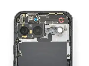
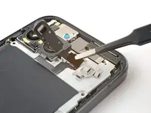
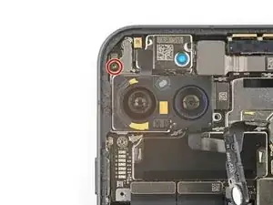
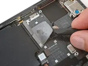
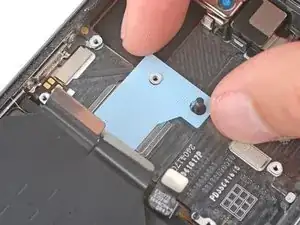
    • Use a 3IP Torx Plus driver to remove the 5.4 mm-long screw securing the antenna board cover.

  18. KhhpXMP5VAFxkcUV
    • Use a pair of tweezers to remove the antenna board cover.

  19. VecruISPWTMmHUVU
    VecruISPWTMmHUVU
    cvdD2OdmlbVXxDCV
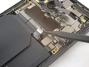
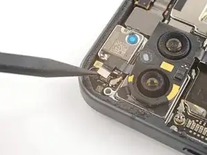
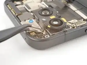
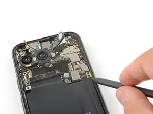
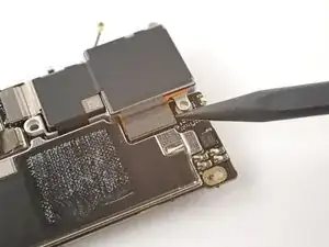
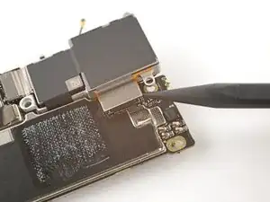
    • Use the tip of a spudger to pry up and disconnect the autofocus connector from the motherboard.

  20. tUbxXrOY4s1cR1El
    tUbxXrOY4s1cR1El
    CtyZxs5FldN3AVXL
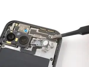
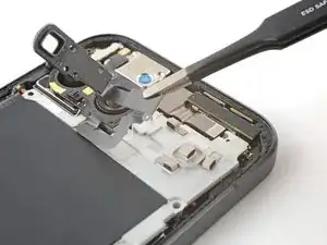
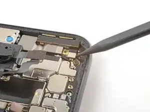
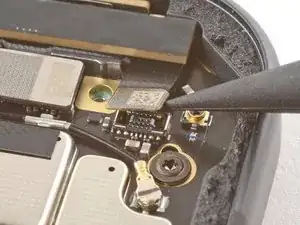
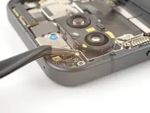
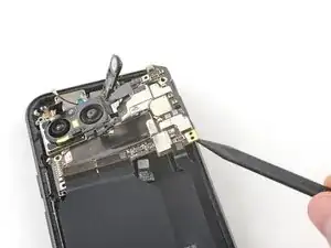
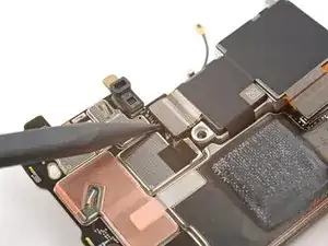
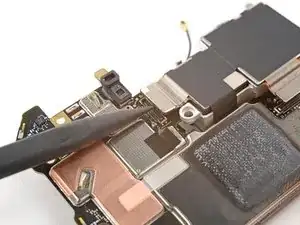
    • Insert one arm of a pair of angled tweezers under the metal neck of the antenna board's coaxial antenna cable.

    • Lift straight up to disconnect the antenna.

  21. kCvJf4xUcMgjjAnY
    kCvJf4xUcMgjjAnY
    MhUtKwuTuA3UlhhV
    • Use the tip of a spudger to pry up and disconnect the front camera press connector.

  22. gIOZxGF65cPnrWEq
    gIOZxGF65cPnrWEq
    kjKPMcEKCvInChEO
    WawuWWTb2ewKMBeH
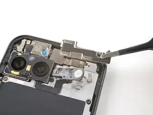
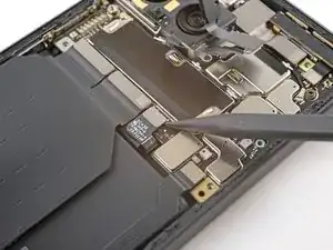
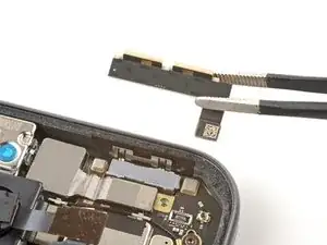
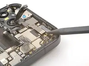
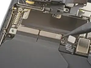
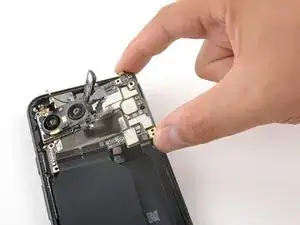
    • Use the tip of a spudger to pry up and disconnect the top two interconnect cable press connectors from the bottom edge of the motherboard.

  23. RJUFPlggJ6Aijoi3
    • Remove the two screws securing the motherboard:

    • One 2.9 mm-long 3IP Torx Plus screw

    • One 5 mm-long standoff screw

  24. aHWGOllcBDABmmFD
    aHWGOllcBDABmmFD
    DIZuB2aPP12DnJgN
    mqKnpj1aiXnuLxSe
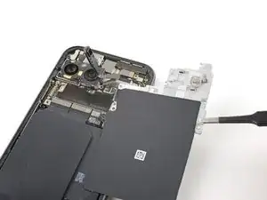
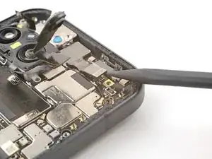
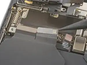
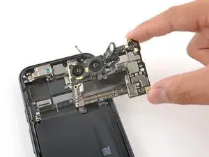
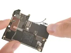
    • Insert the tip of a spudger underneath the bottom right corner of the motherboard.

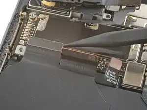
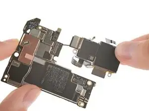
    • Lift up with the spudger to dislodge the motherboard.

    • Lift the motherboard up until you can grip it with your fingers.

  25. AHxYuKVhbh2NIxpc
    AHxYuKVhbh2NIxpc
    QEdbIINfC3OI3VpZ
    • Remove the motherboard.

  26. HLgFORY2mIa1sDZl
    HLgFORY2mIa1sDZl
    YR2uNUYvnNxgFihn
    wrYCerldGoGcDCeu
    • During reassembly:

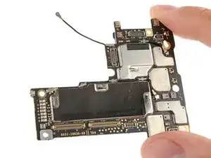
    • Check the condition of the logic board thermal pad—it will either be on the bottom of the logic board or on the frame.

    • If the pad is undamaged, skip the rest of this step.

    • If the pad is damaged, use the flat end of a spudger to scrape it up and remove it.

    • Use isopropyl alcohol (greater than 90%) and a microfiber cloth to remove all thermal pad residue from the frame and bottom of the logic board.

    • Apply a new thermal pad to its spot on the frame.

  27. mXh5HmFt2eiOnZCv
    mXh5HmFt2eiOnZCv
    Zg4NsJrhiXE6FYXU
    • Use the tip of a spudger to pry up and disconnect the flash connector from the motherboard.

  28. JwfV5D4jPkSBmg6j
    JwfV5D4jPkSBmg6j
    oqYLJy3vadGFY2tC
    • Use the tip of a spudger to pry up and disconnect the wide camera.

  29. JPHR2dWM2pMAvCP1
    JPHR2dWM2pMAvCP1
    RWy6YGAVFUObGEkF
    • Use the tip of a spudger to pry up and disconnect the ultrawide camera.

  30. Ar5TDqWuqVu6iyjO
    Ar5TDqWuqVu6iyjO
    2VSSmOGkdWHiyX5w
    • Remove the rear camera module from the motherboard.

  31. 2IEd1uEoilIegsNB
    • Only the motherboard remains.

  32. MOyb4O2dQFRyuyA5
    MOyb4O2dQFRyuyA5
    p1dMA5GpWi4xlvKq
    UNGmHeneWvXoJmB2
    • Check if there's an autofocus sensor pre‑installed on the top of your replacement rear cameras. If there isn't, follow the remaining steps to remove and transfer the sensor from your old cameras.

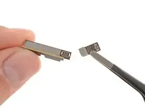
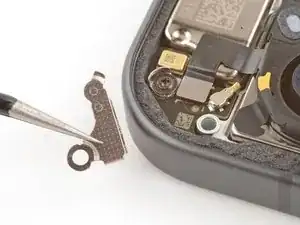
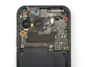
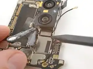
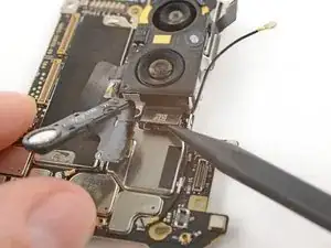
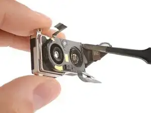
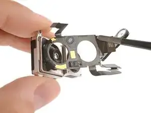
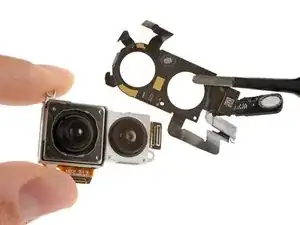
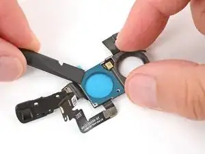
    • Use a pair of tweezers to gently peel the autofocus and flash assembly off of the rear camera module, being very careful not to damage the cable or press connectors.

    • If you're having trouble, use an iOpener or hair dryer to lightly heat the sensor.

    • Only the rear camera module remains.

  33. ChcV4YQDbdhMrZfs
    ChcV4YQDbdhMrZfs
    vW6CysZY6MNSvvK6
    l3fttSMSMUukMDEI
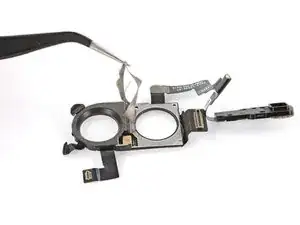
    • Use a spudger and tweezers to remove the two pieces of adhesive from the bottom of the LDAF and flash module.

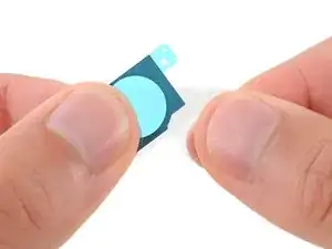
    • Remove the larger clear liners from one of the flash module adhesives.

    • Place the adhesive into place on the bottom of the module and press down firmly with the flat end of a spudger to secure the adhesive.

    • Repeat the process to apply the other piece of flash adhesive.

    • Remove the two remaining blue liners.

  34. DXLTpGeX4SCuL4Cu
    DXLTpGeX4SCuL4Cu
    BOAXYOSicZGd3oGA
    • Be very careful not to touch the camera lenses during this step. If you accidentally do, wipe them with a clean microfiber or lint‑free cloth.

    • If your replacement rear cameras have protective caps or liners, remove them.

    • Carefully lay the sensor over the rear camera and press it into place, securing it with the adhesive.

    • The side with the longer cable should be over the smaller camera.

Conclusion

To reassemble your device, follow these instructions in reverse order starting with this step.

To run a diagnostics test with the built-in Pixel Diagnostic tool, click here.

Take your e-waste to an R2 or e-Stewards certified recycler.

Repair didn’t go as planned? Try some basic troubleshooting, or ask our Pixel 9 Answers Community for help.

Carsten Frauenheim

Member since: 10/03/20

136131 Reputation

0 comments