
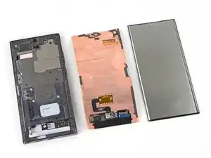
Introduction
Follow this guide to replace a broken, cracked, or non-responsive screen on your Samsung Galaxy S23 Ultra.
Note: This guide shows how to replace the screen by itself. If your replacement part is a screen that's pre-installed on a frame, follow this guide instead.
Warning: This process will destroy your old screen. It requires delaminating the front glass from the display panel. Don't use this guide if you're trying to harvest a screen.
Note: Retaining water resistance after the repair will depend on how well you reapply the adhesive, but your device will lose its IP (Ingress Protection) rating.
Tools
-
-
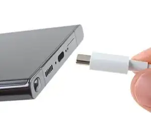
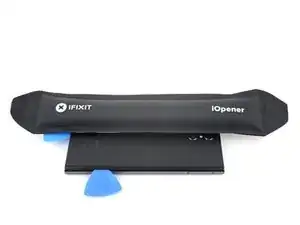
While you wait for the adhesive to soften, note the following:
-
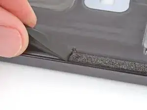
There's adhesive securing the back cover around the perimeter of the frame.
-
-
-
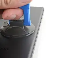
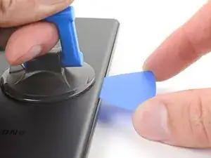
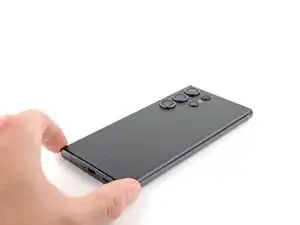
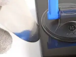
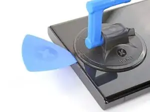
Apply a suction handle to the back cover, as close to the center of the right edge as possible.
-
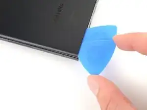
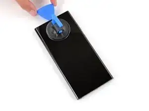
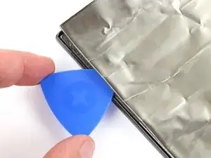
Pull up on the suction handle with strong, steady force to create a gap between the cover and the frame.
-
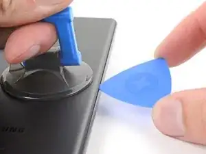
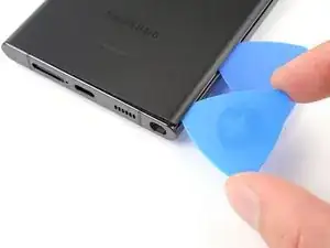
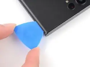
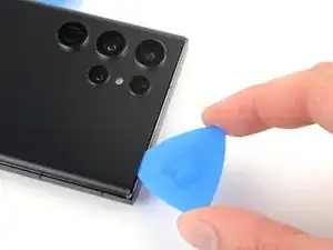
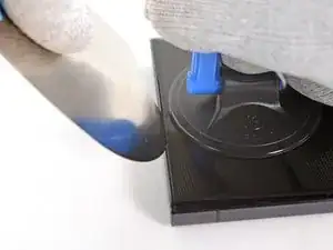
Insert an opening pick into the gap.
-
-
-
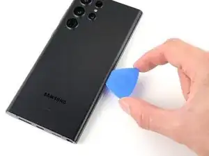
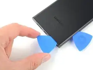
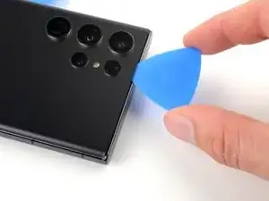
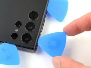
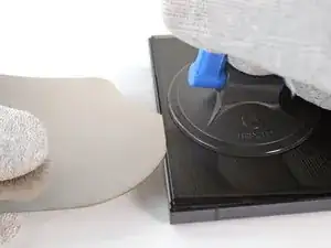
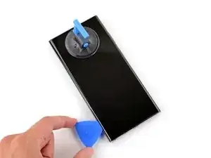
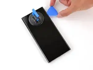
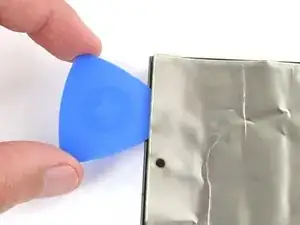
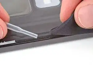
Slide the pick back and forth along the right edge to separate the adhesive.
-
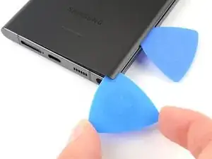
Leave the pick inserted near the bottom right corner to prevent the adhesive from resealing.
-
-
-
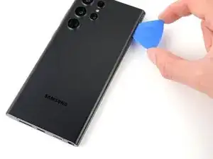
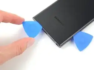
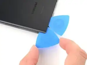
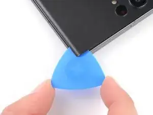
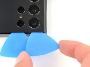
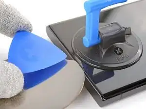
Insert a second opening pick at the bottom right corner.
-
Angle the pick upward to match the curved edge and rotate it around the bottom right corner.
-
-
-
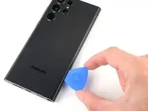
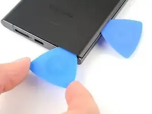
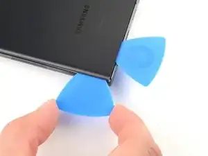
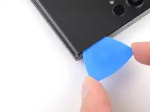
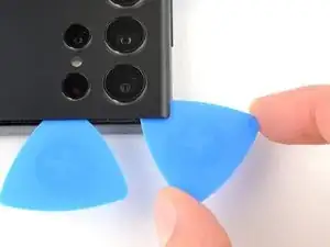
Slide your opening pick to the bottom left corner to separate the adhesive.
-
Leave the pick in the bottom left corner to prevent the adhesive from resealing.
-
-
-
Insert a third opening pick at the bottom left corner.
-
Angle the pick upward to match the curved edge and rotate it around the bottom left corner.
-
-
-
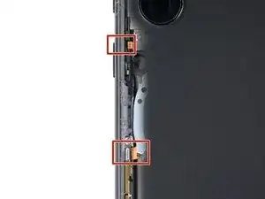
Slide your opening pick along the left edge to separate the adhesive, stopping when you reach the power button.
-
Leave the pick in the left edge to prevent the adhesive from resealing.
-
-
-
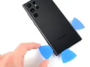
Insert an opening pick in the gap at the top right edge.
-
Angle the pick upward to match the curved edge and rotate it around the top right corner.
-
-
-
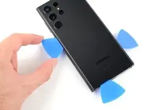
Slide the pick to the top left corner to separate the adhesive.
-
Leave the pick in to prevent the adhesive from resealing.
-
-
-
Insert an opening pick in the gap at the top left edge.
-
Angle the pick upward to match the curved edge and rotate it around the top left corner.
-
-
-
Slide the pick toward the bottom camera to separate through the remaining adhesive, stopping before you reach the power button.
-
-
-
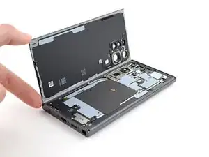
Grab and remove the back cover.
-
Remove any adhesive chunks with a pair of tweezers or your fingers. Apply heat if you're having trouble separating the adhesive.
-
If you're using custom-cut adhesives, follow this guide.
-
If you're using double-sided tape, follow this guide.
-
-
-
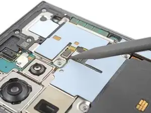
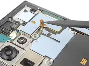
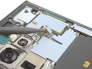
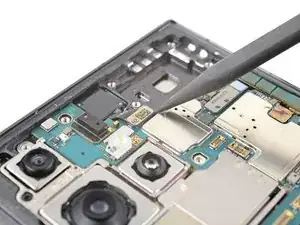
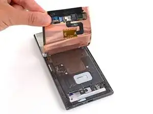
Use the pointed end of a spudger to pry up and disconnect the NFC antenna press connector from the motherboard.
-
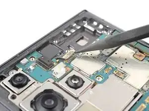
Repeat for the wireless charging coil press connector.
-
-
-
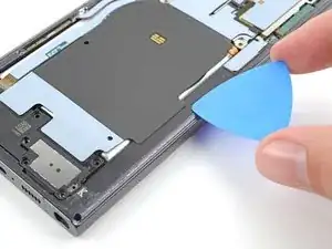
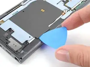
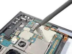
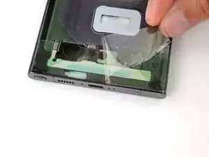
Insert an opening pick between the right edge of the wireless charging coil and the battery.
-
Slide the pick along the right edge to separate the adhesive.
-
-
-
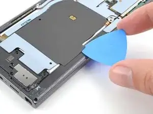
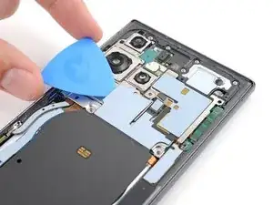
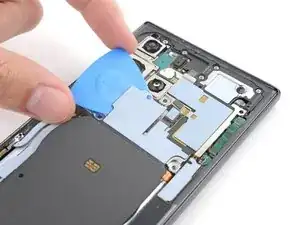
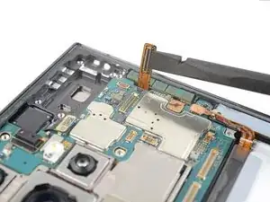
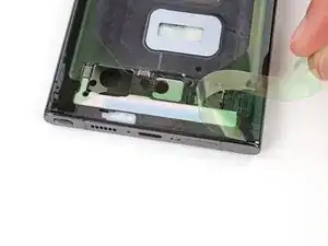
Insert an opening pick between the top edge of the wireless charging coil and the frame.
-
Slide the pick toward the right edge to separate the remaining adhesive.
-
-
-
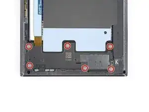
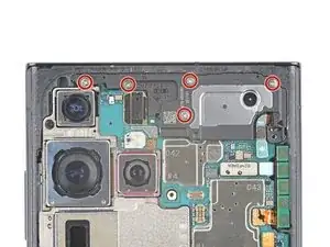
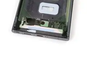
Use a Phillips screwdriver to remove the five 3.5 mm-long screws securing the NFC antenna and charging coil.
-
-
-
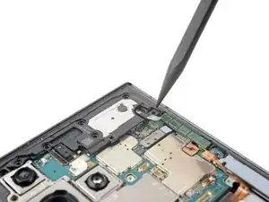
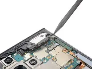
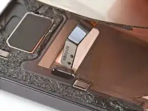
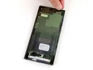
Insert the pointed end of your spudger between the upper right corner of the loudspeaker and the frame.
-
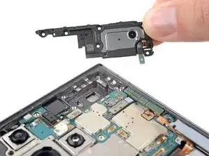
Pry up to unclip the loudspeaker from the frame.
-
-
-
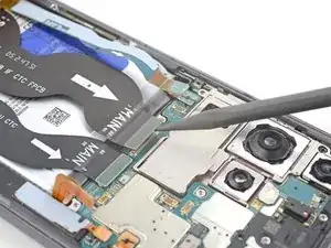
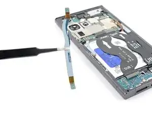
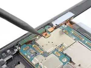
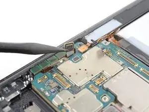
Use your spudger to pry up and disconnect the secondary interconnect cable press connector from the motherboard.
-
Repeat for the primary interconnect cable.
-
-
-
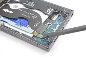
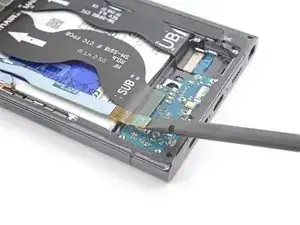
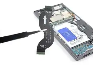
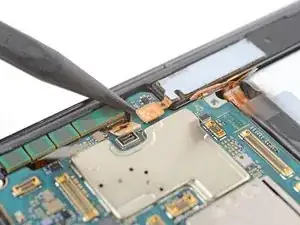
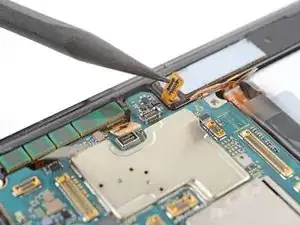
Use your spudger to pry up and disconnect the secondary interconnect cable press connector from the charging board.
-
Repeat for the primary interconnect cable.
-
-
-
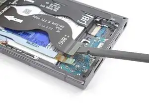
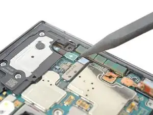
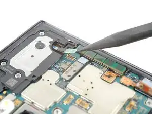
Use the point of your spudger to pry up and disconnect the earpiece speaker press connector.
-
-
-
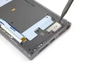
Use a Phillips screwdriver to remove the five 3.5 mm-long screws securing the motherboard cover.
-
-
-
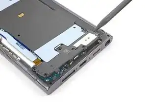
Insert the point of your spudger between the bottom right corner of the motherboard cover and the frame.
-
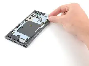
Pry up on the cover to unclip it from the frame.
-
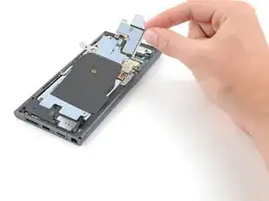
Remove the motherboard cover.
-
-
-
Use the point of your spudger to pry up and disconnect the front-facing camera press connector.
-
-
-
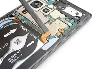
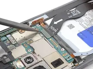
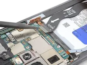
Use the point of your spudger to pry up and disconnect the screen press connector from the motherboard.
-
-
-
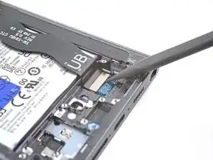
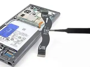
Use the point of your spudger to pry up and disconnect the screen press connector from the display cutout near the bottom of the phone.
-
-
-
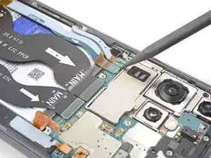
Use the point of your spudger to pry up and disconnect the right 5G mmWave antenna press connector.
-
-
-
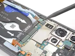
Use the point of your spudger to pry up and disconnect the left 5G mmWave antenna press connector.
-
-
-
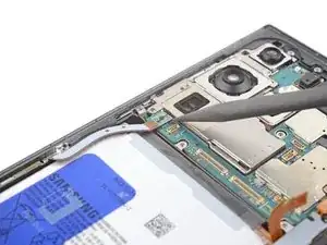
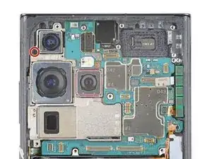
Use your Phillips screwdriver to remove the single 4 mm-long screw securing the motherboard.
-
-
-
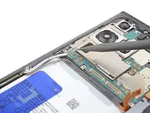
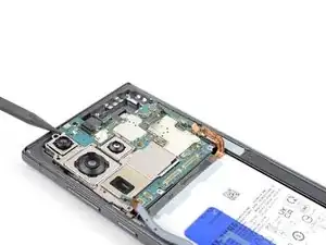
Insert the point of your spudger between the top left of the motherboard and the frame.
-
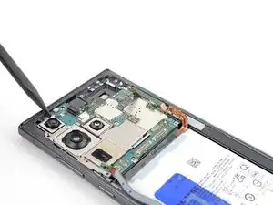
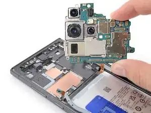
Pry the motherboard up until you can grab it with your fingers.
-
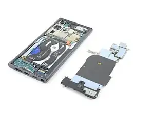
Grab the motherboard and remove it from the frame.
-
-
-
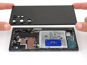
Place the back cover back on the frame to protect the battery and your phone's internals from damage.
-
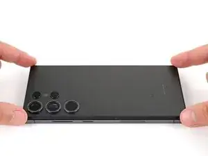
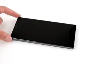
Flip your phone over so the screen is facing up.
-
-
-
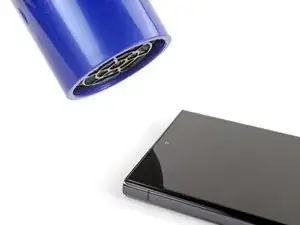
Use a hair dryer or heat gun to heat the top edge of the screen just until it's hot to the touch.
-
-
-
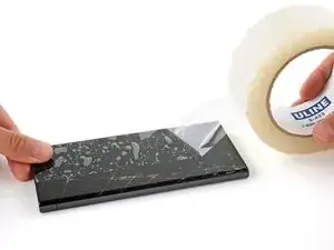
If your screen is badly cracked, lay overlapping strips of packing tape over the glass to protect yourself and make disassembly easier.
-
-
-
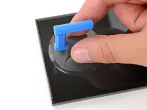
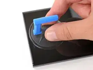
Apply a suction handle to the center of the screen's top edge, as close to the edge as possible.
-
-
-
Don't grip the iFlex or similar metal tools by the edges—they're very sharp.
-
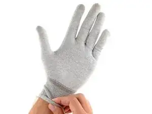
The front glass can shatter and throw shards of glass around your workspace. Consider wearing gloves and safety glasses to protect yourself.
-
-
-
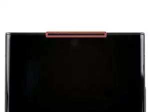
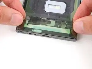
Insert the iFlex at a downward angle into the earpiece speaker gap between the top edge of the front glass and frame.
-
-
-
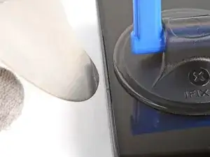
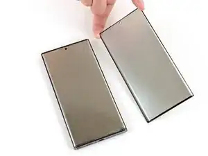
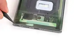
Lift the suction handle with strong, steady force and lower the iFlex so it slides under the front glass, between the glass and the display panel. A large portion of the front glass may separate—that's fine. You may see the tip of the iFlex under the glass.
-
-
-
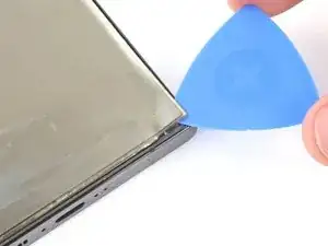
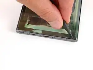
Slide the opening pick around the perimeter of the back glass to separate the adhesive securing it to the display panel.
-
-
-
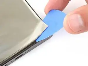
Slide an opening pick under the bottom corner of the display panel and lift to separate the adhesive.
-
-
-
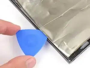
Continue sliding your opening pick under the perimeter of the display panel to separate the remaining adhesive.
-
-
-
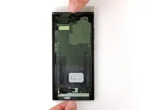
Slowly peel up the display panel, making sure you thread the cable near the top left corner through its cutout in the frame.
-
-
-
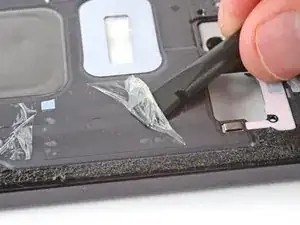
Check the bottom half of the frame for pieces of thin plastic left behind by the screen.
-
Use a spudger and tweezers to scrape up and remove the plastic.
-
-
-
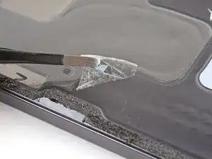
In order for your new screen to adhere properly, you'll need to thoroughly remove all of the old screen adhesive and its residue.
-
Use a spudger to scrape up and remove all of the old screen adhesive from the perimeter of the frame.
-
Once all of the old adhesive is removed, use high concentration (>90%) isopropyl alcohol and a microfiber cloth to remove any remaining adhesive residue.
-
Allow the alcohol to dry completely before continuing.
-
-
-
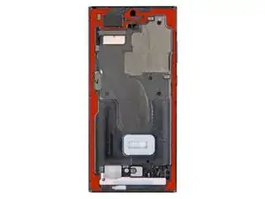
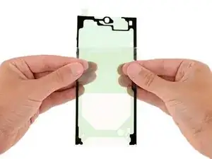
Before applying the larger piece of replacement adhesive, it's helpful to see how it will be oriented.
-
Hold the adhesive so the clear liner is on the bottom and test-fit it against the frame to find the proper orientation.
-
-
-
Peel down the top half of the larger, clear liner to expose the adhesive—don't remove the whole liner yet.
-
-
-
Carefully place the top edge of the adhesive onto the frame.
-
Once the top edge is aligned and applied, slowly lay the rest of the adhesive onto the frame, peeling the clear liner down and away as you go.
-
-
-
Use your fingers to firmly press the adhesive into place on the frame.
-
Use the flat end of a spudger to further secure the adhesive.
-
-
-
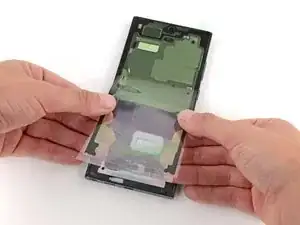
Peel off the larger, more rigid clear‑liner on the second piece of adhesive.
-
With the adhesive's remaining liners facing up, carefully lay the adhesive into place along the bottom edge of the frame.
-
-
-
Use the point of a spudger to firmly press along the entire piece of adhesive to secure it to the frame.
-
-
-
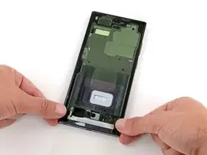
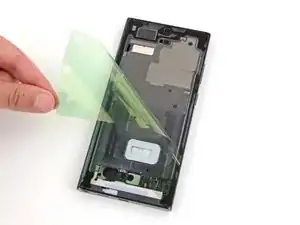
Remove the two remaining liners (one clear, one green) from the small, bottom‑edge adhesive.
-
-
-
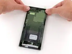
Use the pull tab in the top right corner to peel and remove the remaining liner from the main adhesive.
-
-
-
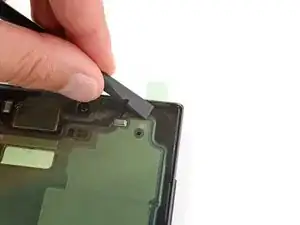
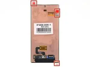
Carefully check the underside of your replacement screen for any liners or tabs and remove them.
-
Thread the screen cable through its cutout near the top left corner of the frame and lay the screen into place.
-
Press firmly around the perimeter of the screen to secure it.
-


To reassemble your device, follow these instructions in reverse order starting with this step.
Take your e-waste to an R2 or e-Stewards certified recycler.
Repair didn’t go as planned? Try some basic troubleshooting, or ask our Answers community for help.

2 comments
where the hell is the screen for purchase, dingus?
🤣🤣🤣🤣🤣🤣🤣 Good point. I would not deal with this though. Not worth 250$ +tx for samsung to do it, or trade in on next phone