Introduction

Use this guide to replace the USB-C port and daughterboard in your Samsung Galaxy S23.

The USB-C port is soldered to the daughterboard, so replacing either part requires replacing the entire assembly.

Note: Retaining water resistance after the repair will depend on how well you reapply the back cover adhesive, but your device will lose its IP (Ingress Protection) rating.

  1. Sx1u1MHUnCWPfOPw
    Sx1u1MHUnCWPfOPw
    r4GI1cSmWuPkjNCq
    • Allow your phone's battery to drain below 25%, as a charged lithium-ion battery is a potential safety hazard. If your battery is swollen, take appropriate precautions.

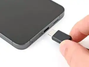
    • Unplug any cables from your phone.

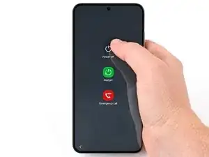
    • Hold the side key and the volume down button, then select "Power off" to turn off your phone.

  2. nEYYVbqZux2EwQTJ
    nEYYVbqZux2EwQTJ
    ptxErRieGRAWS52j
    VQQ4m4GRQWOPYEyV
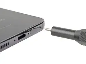
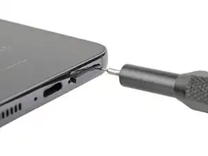
    • Insert a SIM eject tool, bit, or straightened paper clip into the SIM card tray hole on the bottom edge of the phone.

    • Press firmly to eject the tray.

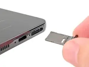
    • Remove the SIM card tray.

    • If you accidentally inserted the SIM eject tool into a microphone hole, don't worry! You most likely didn't damage the microphone.

  3. aCUmlsBGDVXZvvTY
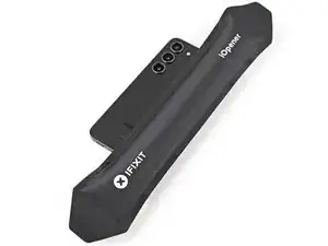
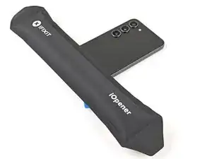
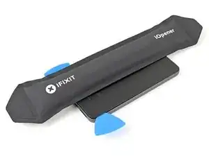
    • Heat an iOpener and apply it to the right edge of the back cover for two minutes to soften the adhesive.

    • A hair dryer, heat gun, or hot plate may also be used, but be careful not to overheat the phone—the display and internal battery are susceptible to heat damage.

  4. G2FmZeHtsHceMDsu
    G2FmZeHtsHceMDsu
    mKRFEuH6lOt1ZZ1C
    pey3XiXRmPT4PjaL
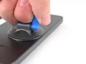
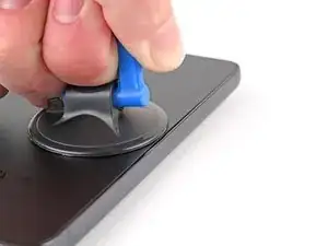
    • Apply a suction handle to the back cover, as close to the center of the right edge as possible.

    • Pull up on the suction handle with strong, steady force to create a gap between the cover and the frame.

    • If you have trouble creating a gap, apply more heat to further soften the adhesive. Follow the iOpener instructions to avoid overheating.

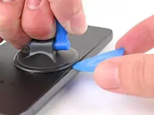
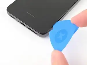
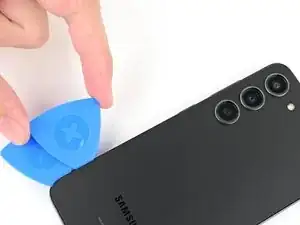
    • Insert an opening pick into the gap.

    When inserting the first pick, I partly cracked my backplate: if the opening is not long enough, inserting the pick puts vertical pressure on the backplate and it'll crack. I suggest slicing a few centimeters of glue before inserting the pick.

    Stéphane L -

  5. nDEsI1PNNtcjfS3t
    nDEsI1PNNtcjfS3t
    SWcikwFOUNgOID5n
    hoYHK4SeDRBQWdXR
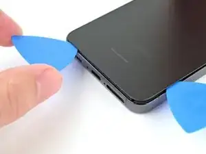
    • Slide the pick back and forth along the right edge to separate the adhesive.

    • Leave the pick inserted near the bottom right corner to prevent the adhesive from resealing.

  6. FNqMYfZU3rLxOxUP
    • Apply a heated iOpener to the bottom edge of the back cover for two minutes.

  7. MtV1RPwoUOADMDE4
    MtV1RPwoUOADMDE4
    ZPTDssnZVp6UKmfO
    Os3gAB2g6VK4aNWL
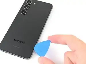
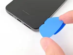
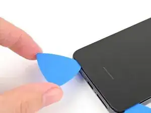
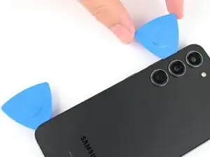
    • Insert a second opening pick at the bottom right corner.

    • Rotate it around the bottom right corner to separate the adhesive.

  8. VEQs2rxVJhClkSFA
    VEQs2rxVJhClkSFA
    sCe5udEVENeZDGpu
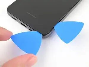
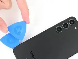
    • Slide your opening pick to the bottom left corner to separate the adhesive.

    • Leave the pick in the bottom left corner to prevent the adhesive from resealing.

  9. KAVn3ZB2VnS5oXrD
    • Apply a heated iOpener to the left edge of the back cover for two minutes.

  10. UHOYZOsDRStYGnlk
    UHOYZOsDRStYGnlk
    QWECeUXwRoZoofCB
    • Rotate the opening pick around the bottom left corner to separate the adhesive.

  11. xjraKNup1SuKZC2W
    xjraKNup1SuKZC2W
    Q34blEeTxpMv3N2g
    RYbTe2Bq1tM3AZXF
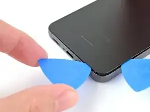
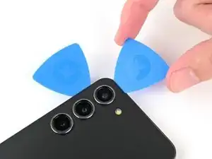
    • Insert a third opening pick at the bottom left corner.

    • Slide your pick toward the top left corner to separate the adhesive.

    • Leave the pick in the top left corner to prevent the adhesive from resealing.

  12. Gb1BNDZW2saggPNj
    • Heat an iOpener and apply it to the top edge of the back cover for two minutes.

  13. FiUVZSPZs5Z11D3S
    FiUVZSPZs5Z11D3S
    MJGmWZWLnigQgWi1
    kvhDsvi4qEOf4y6N
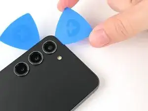
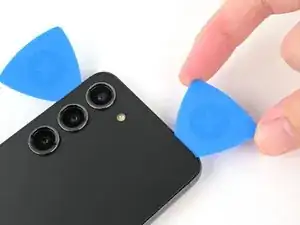
    • Insert a fourth opening pick at the top left corner.

    • Rotate it around the top left corner to separate the adhesive.

  14. OjhkRsdUnoBITAud
    OjhkRsdUnoBITAud
    oDsgnHCQwvRVV4gU
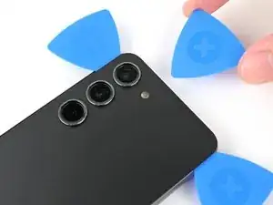
    • Slide your opening pick to the top right corner to separate the adhesive.

    • Leave the pick in the top right corner to prevent the adhesive from resealing.

  15. OSFOsqqrPZIHKJED
    OSFOsqqrPZIHKJED
    BsQHPujpeHHTBHha
    lmpZySfv6VhIDhm1
    • There's a remaining patch of adhesive directly under the flash.

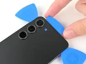
    • Line up the tip of an opening pick with the flash cutout.

    • Slide the opening pick under the top of the back cover until you feel it start to snag on the adhesive.

    • You should see the opening pick through the flash cutout.

    • Keep sliding the pick toward the bottom of the phone until you feel the adhesive completely separate from the back cover.

    • Avoid touching the rear cameras with your pick. Pushing against the lenses risks damaging them.

  16. C3htrnMOEF3Vnf2m
    C3htrnMOEF3Vnf2m
    NlVJyr5umKKTTNXN
    4kBYNVIbCSZjVxLK
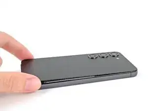
    • Grab and remove the back cover.

    • If your cover is still sticking to the frame, slide an opening pick around the perimeter until the cover completely separates.

    • During reassembly:

    • This is a good point to power on your phone and test all functions before sealing it up. Be sure to power your phone back down completely before you continue working.

    • Remove any adhesive chunks with a pair of tweezers or your fingers. Apply heat and isopropyl alcohol (90% or greater) if you're having trouble removing the adhesive.

    • If you're using custom-cut adhesives, follow this guide.

    • If you're using double-sided tape, follow this guide.

    Just before removing the backplate, take care at the long ribbon cable (in white on the 2nd and 3rd photos, next to the black wireless charging patch). In my case, part of it was gently glued to the backplate for some reason, so double-check that you've separated it from the backplate before attempting to open it, or you might just rip the ribbon cable entirely. In my case, this was preventing me lifting the backplate for more than a few millimeters, and I'm glad I didn't force it before trying to understand exactly what was going on.

    Stéphane L -

  17. YTlnrDD122E2spWU
    YTlnrDD122E2spWU
    joQGLNZHDNeD3E5P
    • Use the point of your spudger to pry up and disconnect the wireless charging coil press connector from the motherboard.

    • To re-attach press connectors, carefully align and press down on one side until it clicks into place, then repeat on the other side. Don't press down on the middle. If the connector is misaligned, the pins can bend and cause permanent damage.

  18. uCvrYLFoCwGBwcye
    uCvrYLFoCwGBwcye
    MEFDGd6MluVtPfhs
    12gDBpAn5THEoCmV
    • Use a Phillips screwdriver to remove the thirteen 3.5 mm‑long screws securing the wireless charging coil and the loudspeaker:

    • Six screws securing the wireless charging coil

    • Seven screws securing the loudspeaker

  19. IOe2bmD3UPygjCZL
    IOe2bmD3UPygjCZL
    6Gn2EmySOrTeittA
    vfbyigJSxkKSuBYs
    • Insert the point of your spudger in the notch at the top left corner of the loudspeaker.

    • Pry up to unclip the loudspeaker from the frame.

  20. PVVU26tV1fTEDVd2
    PVVU26tV1fTEDVd2
    PIdrNsqCheyGC3Ed
    YSvSpXdDGSQhWUgT
    • Use your fingers to lift the loudspeaker away from the frame to fully separate it.

    • Remove the wireless charging coil and loudspeaker from the frame.

    • During reassembly, press around the perimeter of the loudspeaker to clip it to the frame.

  21. NgOcbMfvoJvUYiPR
    NgOcbMfvoJvUYiPR
    c4ZPC2keFhBevYiG
    • Use the point of your spudger to pry up and disconnect the battery press connector.

  22. XytZPseCjBedSjT6
    XytZPseCjBedSjT6
    yGHZ1uHnDhkCHeAC
    KX212cikP6hStjXv
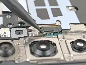
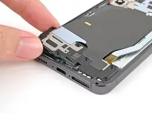
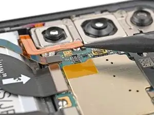
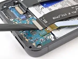
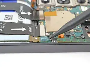
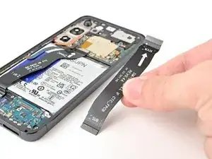
    • Use your spudger to pry up and disconnect the primary and secondary interconnect cable press connectors from the daughterboard.

  23. NJfuUTf4mBeiVJv6
    NJfuUTf4mBeiVJv6
    ZpTnNLgU4t15hBxn
    PK1X46PactyNaRU6
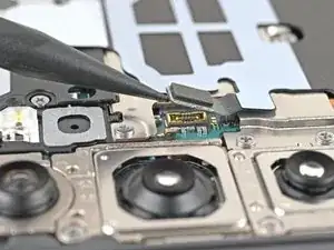
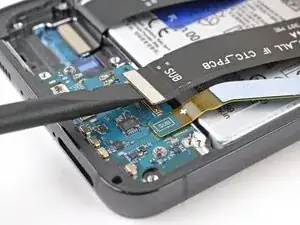
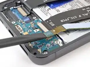
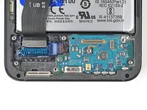
    • Repeat the previous step for the primary and secondary interconnect cable connectors on the motherboard.

  24. Pinw4qyCbeVVkq4J
    Pinw4qyCbeVVkq4J
    JXblv3ujPBgeAWF5
    • Remove both interconnect cables.

  25. TUh4WpVTQrlycktT
    TUh4WpVTQrlycktT
    UPkkWNegvsoPraKe
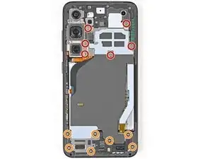
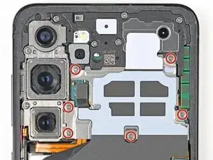
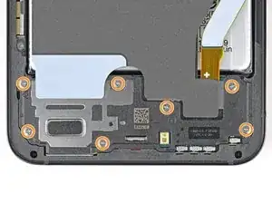
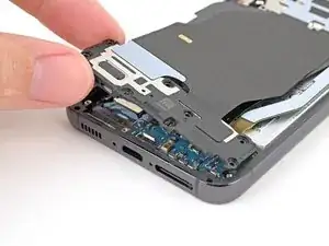
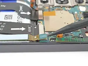
    • Use a Phillips screwdriver to remove the three 3.5 mm‑long screws securing the daughterboard.

  26. 4tgG1SHEWYXDYaSA
    4tgG1SHEWYXDYaSA
    kViriuQbfZIYtMKA
    PhBkOn55nEfkZH4B
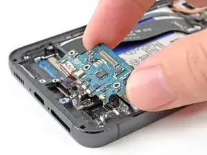
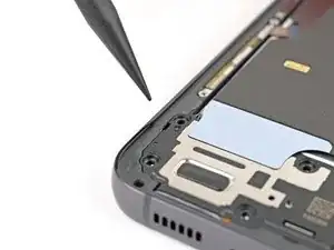
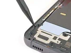
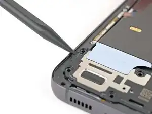
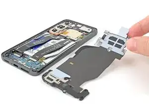
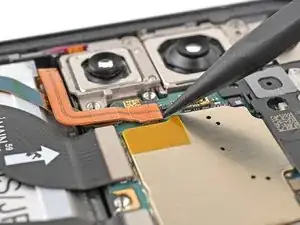
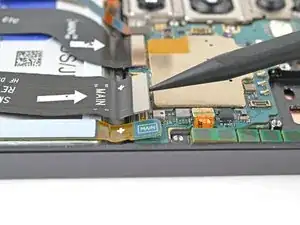
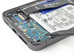
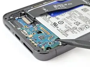
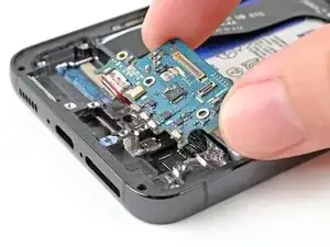
    • Use the point of a spudger to pry up the top right corner of the daughterboard and unclip it from the frame.

    • Don't pry against the battery! Angle your spudger so you pry against the frame.

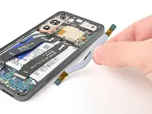
    • Remove the daughterboard.

    • During reassembly, reinsert the USB-C port into its recess at an angle before pressing the daughterboard flat onto the frame.

Conclusion

Compare your new replacement part to the original part—be sure to transfer remaining components and remove adhesive backings from the new part before installing.

To reassemble your device, follow these instructions in reverse order.

Take your e-waste to an R2 or e-Stewards certified recycler.

Repair didn’t go as planned? Try some basic troubleshooting, or ask our Samsung Galaxy S23 Answers Community for troubleshooting help.

Alex Diaz-Kokaisl

Member since: 16/01/22

163004 Reputation

0 comments