Introduction

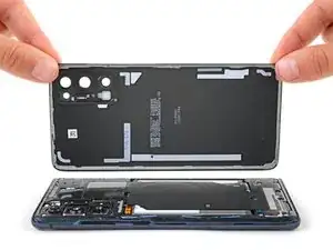
Use this guide to replace the USB-C port and charging board in your Samsung Galaxy S20 FE 5G.

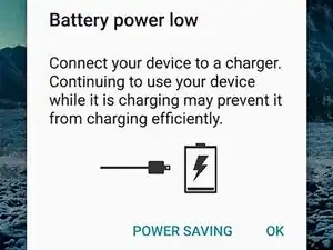
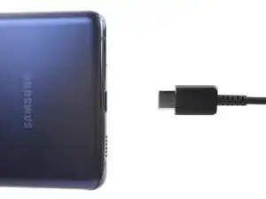
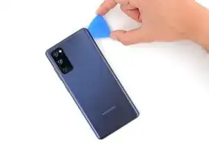
The USB-C port and charging board may need to be replaced if your phone shows that it's not charging when the power cord is plugged in. Sometimes this can be fixed by cleaning dust, dirt, and lint out of the charging port with compressed air and tweezers.

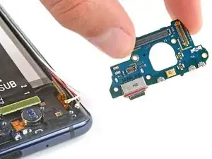
The USB-C port is soldered to the charging board, and they must be replaced as one assembly.

You’ll need replacement back cover adhesive to reassemble your device.

  1. UTes1EGNM5ACPbQo
    UTes1EGNM5ACPbQo
    oUZpsR1CiG2slLBG
    • Before you begin, let your battery drain below 25%—a charged lithium-ion battery can be dangerous if accidentally punctured.

    • Power off your phone and unplug any cables.

  2. RvNBJlCUjk1O5oNJ
    • Heat an iOpener and apply it to the bottom edge of the back cover for two minutes.

    • You can also use a hair dryer—but be careful, as extreme heat will warp the back cover.

  3. kVu4cFJWJFQAQfcT
    kVu4cFJWJFQAQfcT
    NIJESDgeOM2hFQxD
    2HF31o4evqhNWljd
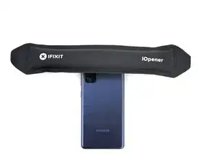
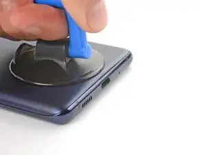
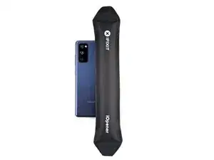
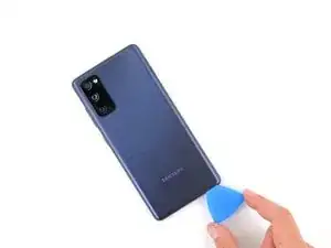
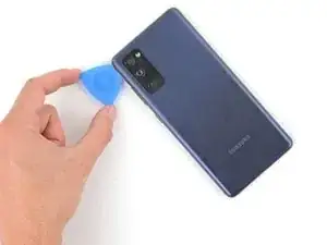
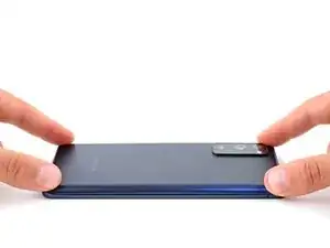
    • Apply a suction cup to the center of the back cover's bottom edge, as close to the edge as possible.

    • Pull up on the suction handle with strong, steady force to create a gap between the cover and frame.

    • This will require significant force. If you're having trouble, apply more heat and try again.

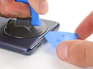
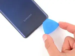
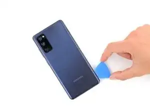
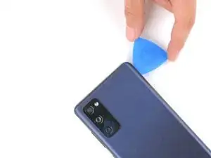
    • Insert an opening pick in the gap.

  4. G6Fd4TCWFQoaOrQF
    G6Fd4TCWFQoaOrQF
    kp1NkUDJSfcjZDKg
    oHdQnfUDXUXC4mPa
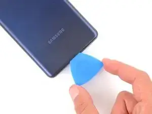
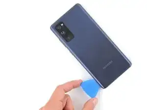
    • Slide the opening pick along the bottom edge to slice the adhesive securing the back cover.

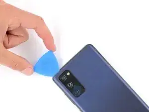
    • Leave the opening pick inserted in the bottom right corner to prevent the adhesive from resealing.

  5. 5fiCUF6qPgykHEep
    • Apply a heated iOpener to the right edge of the back cover for two minutes.

    • You can also use a hair dryer—but be careful, as extreme heat will warp the back cover.

  6. 4KYxP5vKutacDXZJ
    4KYxP5vKutacDXZJ
    U4rNJPkypfTM1N1J
    2YuTPJTd6RjPDQvF
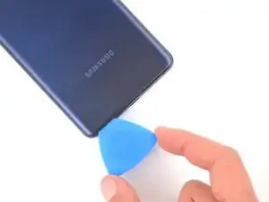
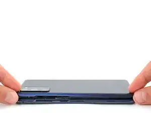
    • Slide the opening pick around the bottom right corner and all the way up the right edge to slice the adhesive.

    • Leave the opening pick inserted in the top right corner.

  7. YYndAO5lBNvZ5gXe
    • Apply a heated iOpener to the top edge of the back cover for two minutes.

    • You can also use a hair dryer—but be careful, as extreme heat will warp the back cover.

  8. 4yNKFd3JWewqTSjm
    4yNKFd3JWewqTSjm
    6h5UBZifAs22tg2N
    • Slide the opening pick around the top right corner and along the top edge to slice the adhesive.

    • Leave the pick inserted in the top left corner.

  9. ILFik3pN1HP3yvUr
    • Apply a heated iOpener to the left edge of the back cover for two minutes.

    • You can also use a hair dryer—but be careful, as extreme heat will warp the back cover.

  10. 3CiEpml6TSqIMCZk
    3CiEpml6TSqIMCZk
    CAJcsIAbQCpCHWh5
    iJkLjx3mywfKX3IW
    • Slide the opening pick around the top left corner and all the way down the left edge to slice the remaining adhesive.

  11. GGYFahESSVO2AqMX
    GGYFahESSVO2AqMX
    RIhO1AGkj6GDpNvL
    • Remove the back cover.

    • If the back cover is still stuck to the frame, slide an opening pick around the perimeter to separate any remaining adhesive.

  12. nbIjnxMZVxxOAWap
    nbIjnxMZVxxOAWap
    pIUqujkFExC5yWXc
    BcRCXLN1oM6UvXQB
    • During reassembly, this is a good point to power on your device and test all functions before sealing it up. Be sure to power it back down completely before you continue working.

    • If you're reinstalling your old back cover:

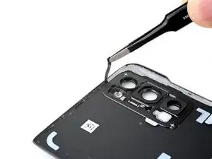
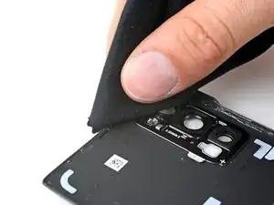
    • Use tweezers or your fingers to peel off the old adhesive from the back cover and frame.

    • Use highly-concentrated isopropyl alcohol (over 90%) and a microfiber cloth to remove any remaining adhesive residue.

    • Follow this guide to apply new custom-cut adhesive.

    • If you're installing a new back cover, peel off the liners and press firmly around the perimeter to secure the back cover to the frame.

  13. gH3KpMQWMR3CYgaS
    gH3KpMQWMR3CYgaS
    uVOCpOTrqNJnKRLL
    4fEy2KCrBKo2MCna
    • The wireless charging assembly includes the motherboard cover, wireless charging coil, and loudspeaker. They're held together with graphite tape and should be removed as one piece.

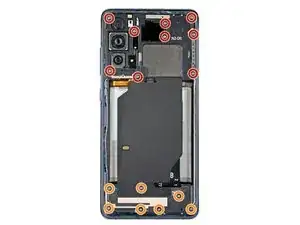
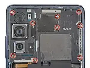
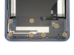
    • Use a Phillips screwdriver to remove the 16 screws securing the wireless charging assembly:

    • Nine 4 mm-long screws securing the motherboard cover

    • Seven 4.5 mm-long screws securing the loudspeaker

  14. hDoukfwyM5CHoBwr
    hDoukfwyM5CHoBwr
    UxOuRXyAv3pxGIG3
    dND6KIMBvOhJryZF
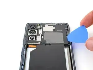
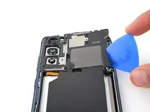
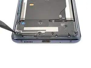
    • Insert a pick under the bottom right edge of the motherboard cover.

    • Twist the pick to release the clips securing the cover.

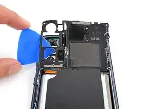
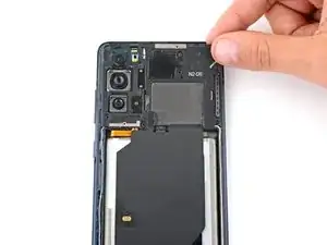
    • Insert and twist the opening pick on the bottom left edge of the cover to release the remaining clips.
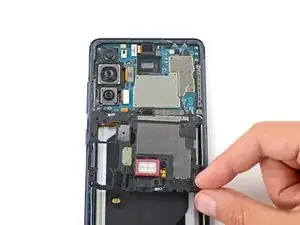
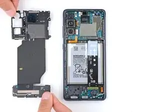
    • During reassembly, press down firmly around the perimeter of the motherboard cover to engage the clips.

  15. FCsFVrBcqup6pLcD
    FCsFVrBcqup6pLcD
    GFh1T4GO2Ilma3yX
  16. gt1oRFcEb3SaQDnR
    gt1oRFcEb3SaQDnR
    dJMTsNNxQEVI2CGa
    P4sMWZDyJKqIH2We
    • Use the flat end of a spudger to pry up and disconnect the battery and wireless charging press connectors from the motherboard.

    • To re-attach press connectors like this one, carefully align and press down on one side until it clicks into place, then repeat on the other side. Don't press down in the middle. If the connector is misaligned, the pins can bend and cause permanent damage.

  17. GcHToTSFVLcrSLXt
    GcHToTSFVLcrSLXt
    XBYfjxRCEswAGryX
    4q1kPPTOBYZXvghn
    • Insert the point of a spudger between the bottom left corner of the loudspeaker and the frame.

    • Pry up to release the clips securing the left edge of the loudspeaker.

    • Pry up the bottom right corner of the loudspeaker to release the remaining clips.

    • During reassembly, press down firmly around the perimeter of the loudspeaker to engage the clips.

  18. o4kbXqE24NFDoVq2
    o4kbXqE24NFDoVq2
    XqFVTWBqpv6qZTlo
    1UNESZuiFR2NipHq
    • Remove the wireless charging assembly.

  19. NOYfgKSgfYMVSKeg
    NOYfgKSgfYMVSKeg
    ueV6xDbPAelpOCMg
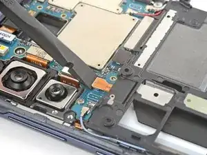
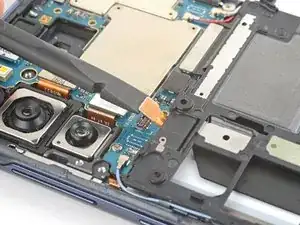
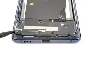
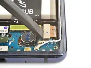
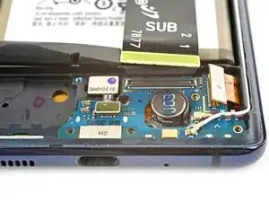
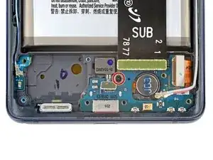
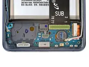
    • Use the flat end of a spudger to pry up and disconnect the display cable press connector from the charging board.

  20. 6PaPJp4IXJWaIC4V
    6PaPJp4IXJWaIC4V
    IhDDM2L3MEYPnC6Z
    m3xqVZVyWSXOVU5I
    • Use a spudger to disconnect the fingerprint sensor and interconnect cable press connectors.

  21. cnupcGKDlpcQ5Rkb
    cnupcGKDlpcQ5Rkb
    aKneuoOJOL3HxTAV
    SYrqtxwQSktTOh62
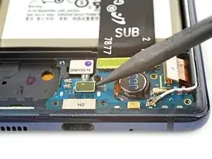
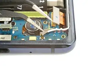
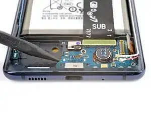
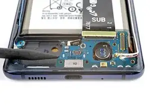
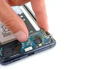
    • Slide one arm of your angled tweezers under the head of the white antenna cable.

    • Gently lift straight up to disconnect the cable.

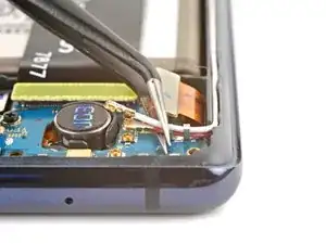
    • Use the same process to disconnect the red antenna cable.

    • To reattach antenna connectors like these, align the connector over its socket and press down with the flat end of a spudger. The connector should snap into place. This can be tricky and may take a few tries.

  22. iM1gAain2edT2Nnw
    iM1gAain2edT2Nnw
    rZ2EG34GpNjSkWKE
    • Gently lift the red and white antenna cables out of their clips on the charging board.

    • During reassembly, make sure the antenna cables are in their channels on the right edge of the phone before pressing them into their clips.

  23. 3nLPC2Rt1mG5rkYY
    3nLPC2Rt1mG5rkYY
    BNyCo5KFfKsvRTi2
    • Use a Phillips screwdriver to remove the 3.5 mm-long screw securing the charging board.

  24. F1NIqKeSH165kCgU
    F1NIqKeSH165kCgU
    EVoASwVAHYIMYyIl
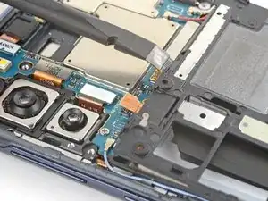
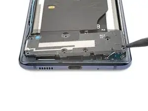
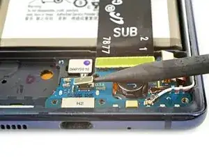
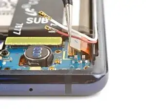
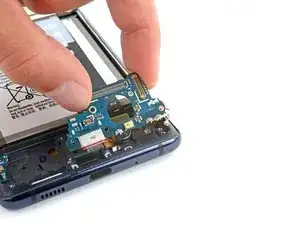
    • Use a spudger to pry up the left side of the charging board until you can grip it with your fingers.

  25. vuk5VwKjNkB2sVEA
    vuk5VwKjNkB2sVEA
    HIT12MPvBwMmP2jp
    5ykIFFTKt1pZhcrP
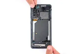
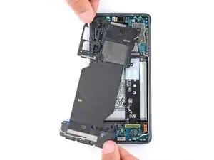
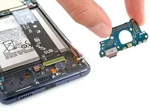
    • Grip the charging board by its top edge and pull it out of its recess at a 45-degree angle.

    • During reassembly:

    • Make sure the five cables that connect to the motherboard are out of the way so they don't get stuck under the board.

    • Insert the charging board at a downward angle and guide the USB-C port into its recess.

    • Push the charging board down firmly until it's snug in its recess.

Conclusion

Compare your new replacement part to the original part—you may need to transfer remaining from the new part before you install it.

To reassemble your device, follow these instructions in reverse order.

Take your e-waste to an R2 or e-Stewards certified recycler.

Repair didn’t go as planned? Try some basic troubleshooting, or ask our Answers community for help.

Spencer Day

Member since: 14/09/22

95583 Reputation

0 comments