Introduction

Prerequisite guide for removing the motherboard in the Samsung Galaxy S23+.

  1. y1WbXuG2sqkNXGFo
    y1WbXuG2sqkNXGFo
    r4GI1cSmWuPkjNCq
    • Allow your phone's battery to drain below 25%, as a charged lithium-ion battery is a potential safety hazard. If your battery is swollen, take appropriate precautions.

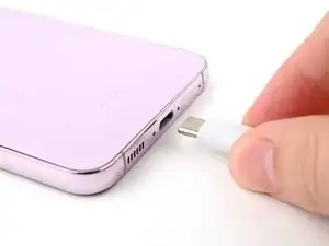
    • Unplug any cables from your phone.

    • Hold the side key and the volume down button, then select "Power off" to turn off your phone.

  2. HCOVZteHN5ZRqDiC
    • Heat an iOpener and apply it to the right edge of the back cover for two minutes to soften the adhesive.

    • A hair dryer, heat gun, or hot plate may also be used, but be careful not to overheat the phone—the display and internal battery are susceptible to heat damage.

  3. MpcTtml5GAh6A6hQ
    MpcTtml5GAh6A6hQ
    rfUwQuOfnkWcrDJW
    eqMIWs2IOM6Xe1QE
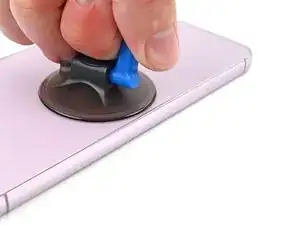
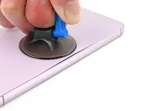
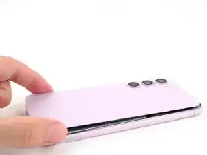
    • Apply a suction handle to the back cover, as close to the center of the right edge as possible.

    • Pull up on the suction handle with strong, steady force to create a gap between the cover and the frame.

    • If you have trouble creating a gap, apply more heat to further soften the adhesive. Follow the iOpener instructions to avoid overheating.

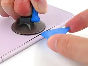
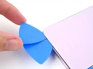
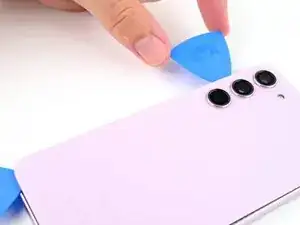
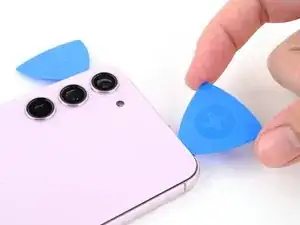
    • Insert an opening pick into the gap.

  4. ajKGG4nAb2wFJpMf
    ajKGG4nAb2wFJpMf
    3fgdJc5RWAIyAknV
    bZXZURDDQZIWspdp
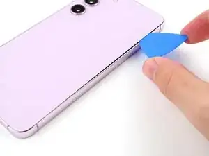
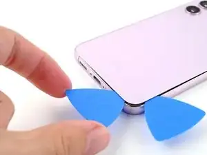
    • Slide the pick back and forth along the right edge to separate the adhesive.

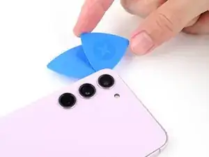
    • Leave the pick inserted near the bottom right corner to prevent the adhesive from resealing.

  5. DoyoCUUiIOrUWEC6
    • Apply a heated iOpener to the bottom edge of the back cover for two minutes.

  6. ufJUDnYgZpJaCLXw
    ufJUDnYgZpJaCLXw
    XiHC4cJEmyMY6Ij1
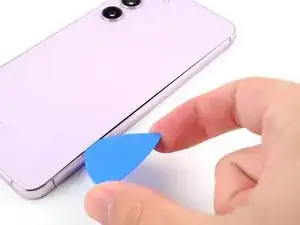
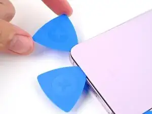
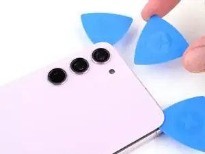
    • Insert a second pick at the bottom right corner.

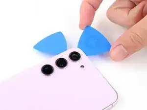
    • Rotate the opening pick around the bottom right corner to separate the adhesive.

  7. gRcrnIAZIQuAgyiq
    gRcrnIAZIQuAgyiq
    fTSTYHKiVLfjFjBB
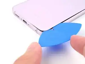
    • Slide the opening pick to the bottom left corner to separate the adhesive.

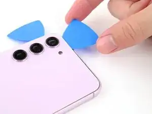
    • Leave the pick in the bottom left corner to prevent the adhesive from resealing.

  8. eO4cLQUBAlQb4VYE
    • Apply a heated iOpener to the left edge of the back cover for two minutes.

  9. Y2CvmJUt6kJUO2yr
    Y2CvmJUt6kJUO2yr
    t3ZaGMKHo5tneOCu
    • Rotate the opening pick around the bottom left corner to separate the adhesive.

  10. BALOQ2PMkjF2qqbR
    BALOQ2PMkjF2qqbR
    vaLBaFcY2tyKmV5M
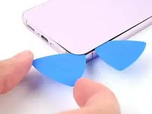
    • Insert a third opening pick at the bottom left corner.

    • Slide your pick toward the top left corner to separate the adhesive.

    • Leave the pick in the top left corner to prevent the adhesive from resealing.

  11. AGjJKKkbhrfO4Lrj
    • Heat an iOpener and apply it to the top edge of the back cover for two minutes.

  12. cJGPdDLnbJAjNCSc
    cJGPdDLnbJAjNCSc
    CfQVslyLCjBEud2P
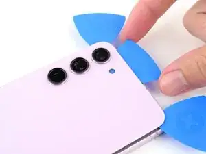
    • Insert a fourth opening pick at the top left corner.

    • Rotate it around the top left corner to separate the adhesive.

  13. 1CqeStxVHRntfoRS
    1CqeStxVHRntfoRS
    JwPwuOIDBFeXOQDp
    • Slide your opening pick to the top right corner to separate the adhesive.

    • Leave the pick in the top right corner to prevent the adhesive from resealing.

  14. Gy6BBTbaBJ3ZwlhQ
    Gy6BBTbaBJ3ZwlhQ
    Jk3DWg5NERYA3LfJ
    QlpsYj4BQ1TPgxrP
    • There's a remaining patch of adhesive directly under the flash.

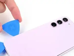
    • Line up the tip of an opening pick with the flash cutout.

    • Slide the opening pick under the top of the back cover until you feel it start to snag on the adhesive.

    • You should see the opening pick through the flash cutout.

    • Keep sliding the pick toward the bottom of the phone until you feel the adhesive completely separate from the back cover.

    • Avoid touching the rear cameras with your pick. Pushing against the lenses risks damaging them.

  15. UQwerhUCepkc1qrv
    UQwerhUCepkc1qrv
    cUkmq2NMr5YGXALN
    mJrpMuDScJuFsp4C
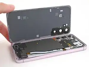
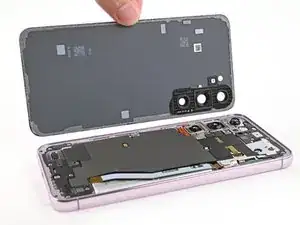
    • Grab and remove the back cover.

    • If your cover is still sticking to the frame, slide an opening pick around the perimeter until the cover completely separates.

    • During reassembly:

    • This is a good point to power on your phone and test all functions before sealing it up. Be sure to power your phone back down completely before you continue working.

    • Remove any adhesive chunks with a pair of tweezers or your fingers. Apply heat and isopropyl alcohol (90% or greater) if you're having trouble removing the adhesive.

    • If you're using custom-cut adhesives, follow this guide.

    • If you're using double-sided tape, follow this guide.

  16. Fk2U1CTXUBYsLjPv
    Fk2U1CTXUBYsLjPv
    4HkHnot4ZAFDIDQ2
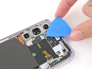
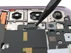
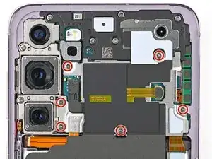
    • Use the point of your spudger to pry up and disconnect the wireless charging coil press connector from the motherboard.

    • To re-attach press connectors, carefully align and press down on one side until it clicks into place, then repeat on the other side. Don't press down on the middle. If the connector is misaligned, the pins can bend and cause permanent damage.

  17. B5tDqrWUng6gqeKF
    B5tDqrWUng6gqeKF
    B2LglWegPnZUVVFE
    • Use the point of a spudger to pry up and disconnect the NFC antenna press connector.

  18. nDeMleEU5tDpPSh2
    nDeMleEU5tDpPSh2
    lfEHUbZvIJvJnUtg
    5dYeKuSPFwjYIIWr
    • Use a Phillips screwdriver to remove the thirteen 3.5 mm‑long screws securing the wireless charging coil and the loudspeaker:

    • Six screws securing the wireless charging coil

    • Seven screws securing the loudspeaker

  19. 1ICB4YFvdcCZYTjD
    1ICB4YFvdcCZYTjD
    Aq2map6tBq5Ur2WD
    CoAumjSOdY5tEpRK
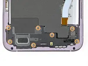
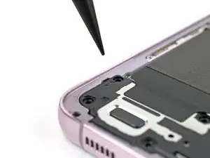
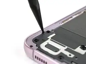
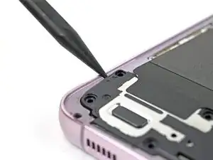
    • Insert the point of your spudger in the notch at the top left corner of the loudspeaker.

    • Pry up to unclip the loudspeaker from the frame.

  20. gWO3qm2jN1QJZVsQ
    gWO3qm2jN1QJZVsQ
    6SJNfeEMZsDkUc2X
    CYYg3oac62lsjBhW
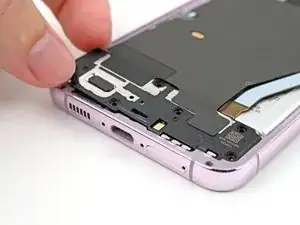
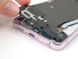
    • Use your fingers to lift the loudspeaker away from the frame to fully separate it.

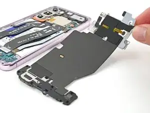
    • Remove the wireless charging coil and loudspeaker from the frame.

    • During reassembly, press around the perimeter of the loudspeaker to clip it to the frame.

  21. d1EJrviiGankuWPd
    d1EJrviiGankuWPd
    RUQpBEUnZABoDJih
    • Use the point of your spudger to pry up and disconnect the battery press connector.

  22. dx1ByBXFOVYmu5XW
    dx1ByBXFOVYmu5XW
    bOWkHHOtApVDVWMH
    • Use the tip of a spudger to pry up and disconnect the earpiece speaker press connector.

  23. DEnZP6jPoEROHhNP
    DEnZP6jPoEROHhNP
    rxbcOirmbQKaLGZD
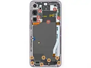
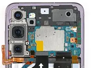
    • Use a Phillips screwdriver to remove the five 3.5 mm‑long screws securing the earpiece speaker.

  24. XCcgfsIBQUvGHuXU
    XCcgfsIBQUvGHuXU
    Eo4NYjxsgHdFgW2c
    bRNrRMNPHbXRdGgp
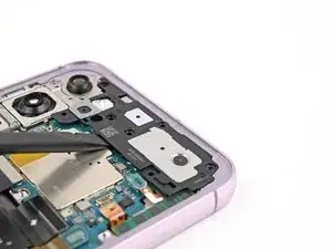
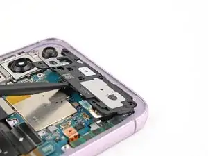
    • Insert the flat end of your spudger between the bottom edge of the earpiece speaker and the sliver shield on the motherboard.

    • Don't insert your spudger anywhere else or you risk dislodging fragile surface‑mounted components.

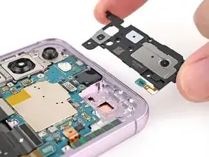
    • Twist the spudger to unclip the earpiece speaker from the frame and remove it.

    • During reassembly, insert the top end of the earpiece speaker into the frame first before pressing down and clipping it back in.

  25. uaNfTWKTpxbEYNuu
    uaNfTWKTpxbEYNuu
    gPvBlBGYvXZFyABE
    HySQYrEuyxYery3u
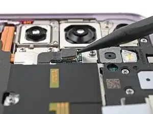
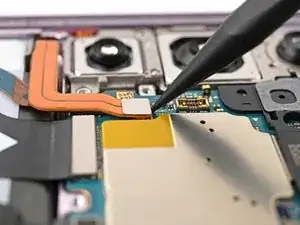
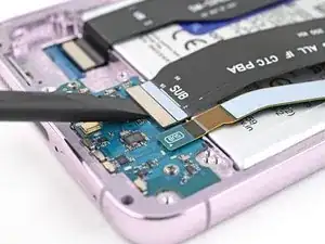
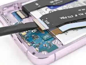
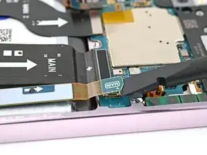
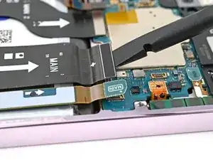
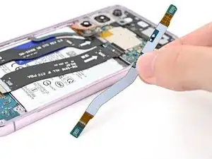
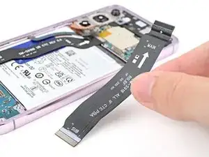
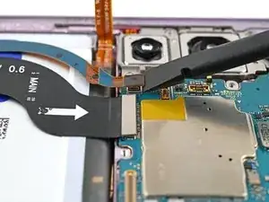
    • Use your spudger to pry up and disconnect the primary and secondary interconnect cable press connectors from the daughterboard.

  26. EZlOkIKtnclwfArP
    EZlOkIKtnclwfArP
    Ni6fQg3BAfuRJDyx
    AOedKv3hfwaBDIJE
    • Repeat the previous step for the primary and secondary interconnect cable connectors on the motherboard.

  27. KBYiKyQ6kkAM4ygX
    KBYiKyQ6kkAM4ygX
    Z6TxVLWpwEvCBxrj
    • Remove the interconnect cables.

  28. MDMwqgFH2DPD5EL5
    MDMwqgFH2DPD5EL5
    2taE21CnmfcBAxxc
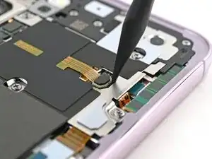
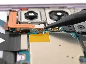
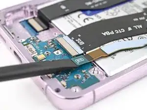
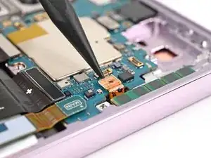
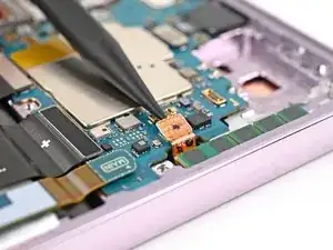
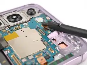
    • Insert the tip of your spudger between the left edge of the antenna press connector and the sliver plate on the motherboard.

    • Fragile surface mounted-components surround this connector. Prying on other edges of this connector risks dislodging them from the board.

    • Pry up and disconnect the antenna press connector.

  29. AkRTLTWUdIOsVnyn
    AkRTLTWUdIOsVnyn
    MVWBpkLyZZQsXGXt
    Fji2F3pyYqBBbUyA
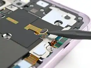
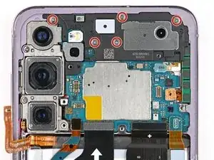
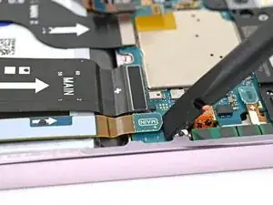
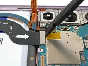
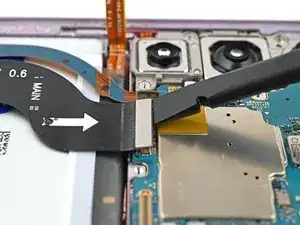
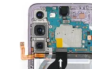
    • Use your spudger to pry up and disconnect the display and 5G mmWave cable press connectors from the motherboard.

  30. r2qeJgnK2AJufo21
    r2qeJgnK2AJufo21
    UL2BZrBRWUnGOCle
    • Use your spudger to pry up and disconnect the front camera press connector.

  31. yhjaFSxilIB5PnCK
    yhjaFSxilIB5PnCK
    HMsyYfELt4gRmlPQ
    • Use a Phillips screwdriver to remove the two 3.5 mm‑long screws securing the motherboard.

  32. mM12MkClyJWBlACu
    mM12MkClyJWBlACu
    DZx3GrW5qLffT1VF
    qcLVmRmLAox5NXvh
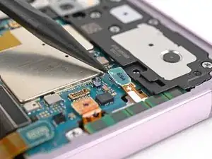
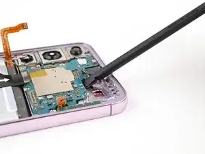
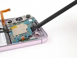
    • Insert the flat end of your spudger between the top edge of the motherboard and the frame, near the earpiece speaker cutout.

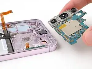
    • Twist the spudger to lift the motherboard up and out of the frame until you can grip it with your fingers.

    • Remove the motherboard.

    • During reassembly, make sure all of the cables are out of the way before placing the motherboard back into the frame.

Conclusion

To reassemble your device, follow these instructions in reverse order.

Alex Diaz-Kokaisl

Member since: 16/01/22

163004 Reputation

0 comments