Introduction

  1. PU61cQeCJQ4ZdMdZ
    PU61cQeCJQ4ZdMdZ
    PVjPT5sIGL3ILEb2
    • Turn the device over and remove the 4 x T5 screws.

  2. ASeCnSD5GvJjE3UZ
    ASeCnSD5GvJjE3UZ
    BtFNvIvQJd2A4U4S
    HvVc2ErHAaKGbFy3
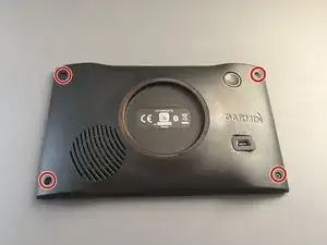
    • Use the prying tool to release the platic clips on the back, going around all the sides.

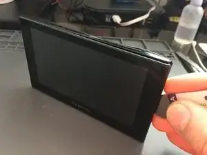
    • Start prying from the sides or the top left corner and work your way around the screen.

    • Be careful at the bottom as the screen connector is still attached. Don't try to fully remove it.

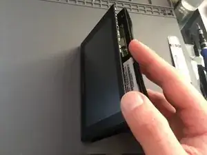
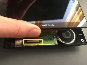
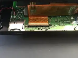
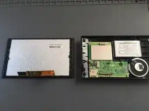
    • Slide the screen slightly upwards to reveal the connector

  3. CUDAiTgRDdUpRZnP
    CUDAiTgRDdUpRZnP
    V6DZ1pVH5HTZSCZV
    L2TQplDJsQYA5LYU
    • Slide up the screen to get access to the connector

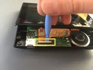
    • Use the plastic prying tool to lift up the latch that secures the ribbon cable and then slide the cable out.

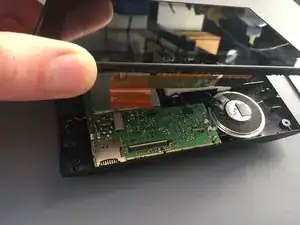
    • Once the cable is out, lift off the screen.

  4. nLQq4tTvwBwtMjTV
    nLQq4tTvwBwtMjTV
    FrnqRFDEgkuIUOew
    uXDRZ3MqsymuymAc
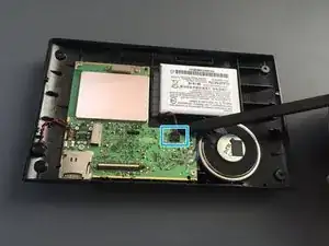
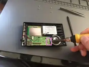
    • Before you can take the logic board out disconnect the battery.

    • Remove the microphone from its socket with a plastic spudger.

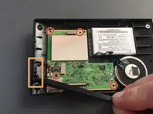
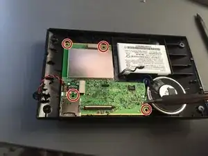
    • Remove the 4 x T5 screws that secures the logic board to the back cover.

  5. MuFawToEXMWOWCTo
    MuFawToEXMWOWCTo
    ngrDhVeqfPCiQkF5
    FNcpKWcm4lmsP3GX
    • Peel off the clear tape from the speaker connections with tweezers.

    • Use your soldering iron to de-solder the two wires from the speaker.

    • Try to minimise the contact time with your iron on the bard to avoid warping and thermal shocking the board. (I used 390 C ~ 740 F)

    • Finally remove the 4 x T5 screws that secure the logic board to the back cover.

  6. IjroTxlQhmxkHq4e
    IjroTxlQhmxkHq4e
    a2xIRHKHRfMGNocR
    • Use the spudger to pop the lociboard out.

  7. thhQJPrUbwDtmHtj
    thhQJPrUbwDtmHtj
    q4fLyCYeQEdbkIGd
    ofySvOIWU6gMIHtp
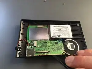
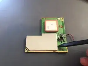
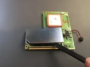
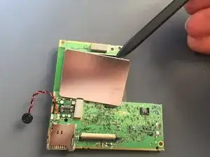
    • To reveal all the components, use the spudger to lift off the metal cover of the protected circuitry

    • Make sure you apply even pressure and don't force the cover off. If it is bent whilst removing, it will be difficult to reassemble.

  8. aVZFUSOUBOatiYJ1
    aVZFUSOUBOatiYJ1
    RqHZ4BY6bojOCNou
    yuNZGQcRTmdQ4gV2
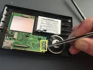
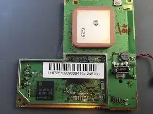
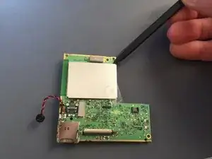
    • Repeat the same step on the back of the logic board.

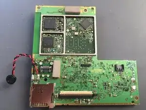
    • Now you successfully exposed all the parts.

Conclusion

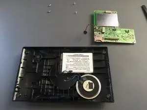
To reassemble your device, follow these instructions in reverse order.

honakrisi

Member since: 28/01/20

3730 Reputation

0 comments