Introduction

If your Canon PowerShot S80 won’t turn on or is experiencing battery-life issues, replacing the motherboard may be the solution.

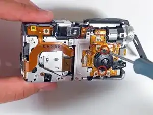
The motherboard is a vital component of your Canon PowerShot S80, responsible for directing power to all camera functions. If it’s damaged or malfunctioning, you may experience poor battery performance or find that your camera won’t turn on at all.

Before diving into the replacement, double-check your battery to rule out any issues. A dead or faulty battery can mimic motherboard problems, so ensure that your battery is in good condition. If the battery is fine, proceed with the motherboard replacement using this guide.

As you follow the steps, handle all components carefully to prevent any further damage to your camera. Pay particular attention in Step 5, where you must carefully detach the screen without damaging the ribbon cable on the left side.

  1. 2rJyRmhfkP3USfwv
    2rJyRmhfkP3USfwv
    VcJXaLpN1UpOOXM3
    • Remove the knot on the wrist lanyard.

    • Remove the battery and the memory card.

  2. eaPYJgRYPXn1cYXr
    eaPYJgRYPXn1cYXr
    6Y4CISKDIqlfwm3C
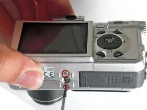
    • Begin removing the screws on the bottom of the outer casing.

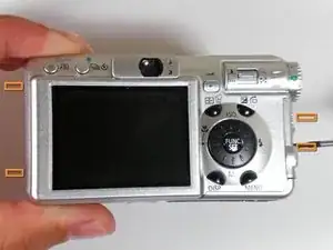
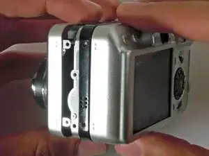
    • Next, remove the rest of the screws from the outer casing.

  3. NKxqiuJ5VcpLsol4
    NKxqiuJ5VcpLsol4
    VhSF2FWl5XybEJmJ
    WOLLFCepUHsdNVlr
    • Gently pull the front cover off of the camera.

  4. ALMjUAxjANTbI1jg
    ALMjUAxjANTbI1jg
    FWuBaHQNt3MATpk3
    AZFYGOaOC1g5fvEK
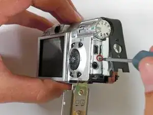
    • Open the "A/V Out Digital" cover. Remove the screw inside.

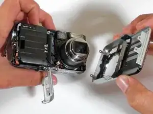
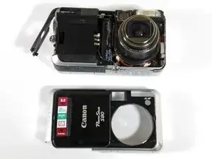
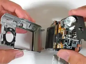
    • Gently pull off the back casing.

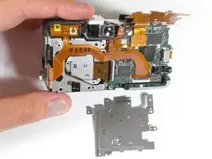
    • Remove the black "L" shaped piece of metal.

  5. KQdmlLTuDOvpTbKG
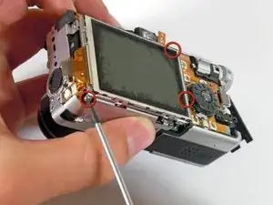
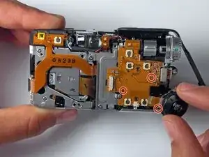
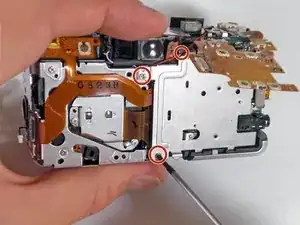
    • Remove the three screws that are holding the screen in place. Free the screen from the underlying components.

    • Be careful with the ribbon wire that is still attached on the left side of the screen.

  6. i3qUdJKijgBM5ih1
    i3qUdJKijgBM5ih1
    guwAvHChptGWrOYM
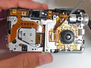
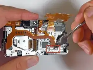
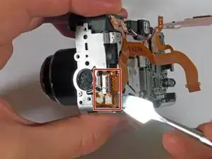
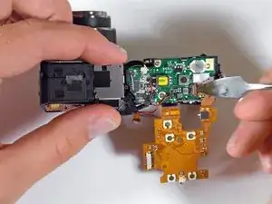
    • With the spudger, gently lift the black flap that is holding the wide ribbon cable wire in place.

    • Unplug the wide ribbon cable.

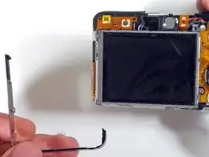
    • Unplug the narrow ribbon cable to free the LCD screen from the camera body.

    The author failed to mention a couple things. First, the screen is in a holder which you remove, then after pulling off some electrical tape, you have to yank the actual screen out. Second, I only had two screws to pull the screen holder out, not three. Third, the thing that you have to pull to get the screen ribbon cable out is actually a tiny black hinge, so don't worry if it suddenly snaps back. Finally, to put the thing back together, it really helps if you have a tweezers to get the ribbon cables back into place.

    and fyi replacement screens available from canon parts department for about 50 bucks.

    steven -

  7. a5oyAQTklFEAysGN
    • Remove the screws holding down the function set button.

  8. eUTMnW3FYju5CM5i
    • Gently pry up the tab with a metal spudger and remove the ribbon cable.

  9. voALKbfrStJvkHOA
    • Be mindful of the pins as you lift up and remove the function/set button.

  10. PMIr4LE4nvVriZUe
    PMIr4LE4nvVriZUe
    u6n5ky3p6OqfA2tW
    VrNhw63Z2pPb5fvR
    • Remove the screws from the metal plate.

    • Gently remove the metal plate.

  11. a6jjDsygbrMvE5aP
    a6jjDsygbrMvE5aP
    ALLasfaDrw6fjXvD
    • Lift the tab connecting the ribbon cable and detach.

  12. KxiXFgcPsFaSOmYI
    KxiXFgcPsFaSOmYI
    lfKSKKfnsvVFCZk1
    • Use a spudger to lift up the ribbon cable tab.

    • Detach the ribbon cable.

  13. S1RUETCVYoGPYGsL
    S1RUETCVYoGPYGsL
    jdwBykMSYywfDqEe
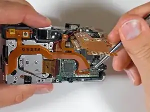
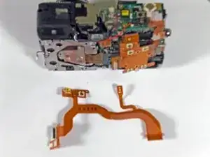
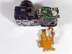
    • Gently remove the entire ribbon cable connection to release the ribbon cable from the camera.

  14. TAvuXqEZoy4TWnW6
    • Unscrew the circuit board from the flash unit.

  15. oqMFhsfyGBoxckUl
    oqMFhsfyGBoxckUl
    I6XTFgHoOBjQRmH2
    YKxSNScCCZDpwfTy
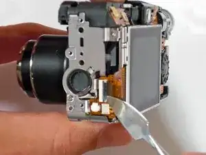
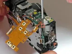
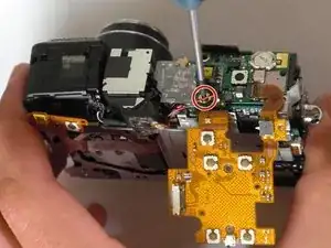
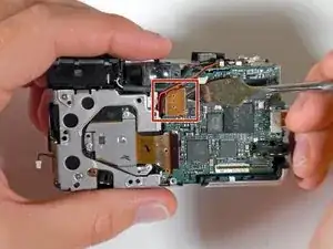
    • Pry up the ribbon cable connection and remove it from the camera.

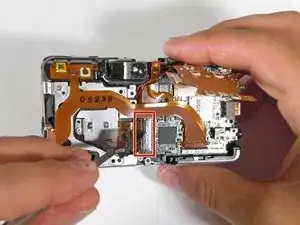
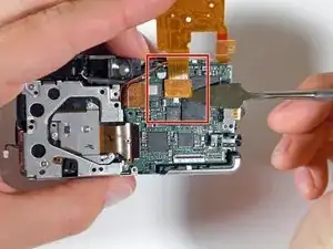
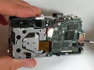
    • Lift the ribbon cable tab and completely detach the cable from the camera.

  16. V2HwcLK3sMpTKrAZ
    • Pry up the connection, being mindful of the light adhesive.

  17. qRMx2COvSLUD4GH3
    • Remove the last screw holding the motherboard to the main body.

  18. BcIUqw1WqnR2IOsJ
    BcIUqw1WqnR2IOsJ
    fuVyrmqNACwnCBnm
    • Use a spudger to gently lift the motherboard from the camera.

Conclusion

To reassemble your device, follow these instructions in reverse order.

BrettH

Member since: 29/10/09

219 Reputation

0 comments